Author: Azya
Posted: 2023-11-13 07:59
Original: Article link
By the time I wrote the previous article, more test units of Tetris-style Brick Games were on the way, and the first one I received looked like this:
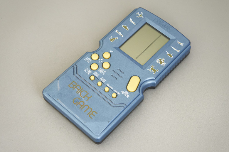
Some Taksun Brick Game
These Tetris devices roughly started appearing for sale in the late 2000s. On this unit, I tried a new method of die decapsulation, wary of repeating the previous failure. The method is as follows: heat the blob of encapsulant with a heat gun until it becomes soft, but not brittle (around 150°C). While continuing to heat, carefully lift the encapsulant with a scalpel, first off the PCB, then with particular caution off the die itself. It sounds simple, but in practice it is not that easy. Even though I succeeded on all three attempts, the risk of damaging the die with a careless movement of the tweezers is still high. On the plus side, there’s no need to use any chemicals, which is very convenient for home work.
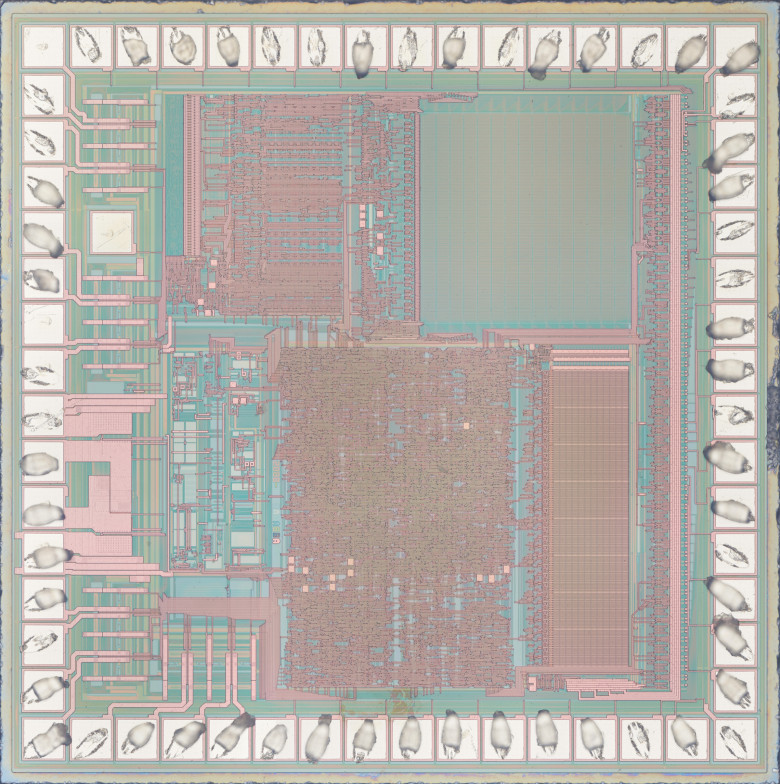
Here is the die of the first Tetris unit:
Full resolution

As expected, the process node is much denser. Unfortunately, there are no identifying markings, only the number “2008,” which is probably the mask fabrication year.
I won’t attempt a deep analysis, but briefly: in the upper right corner there is 7.5 KB of ROM (which would be extremely difficult to read visually through an optical microscope), beneath it 384 B of RAM. In the upper left corner is presumably the instruction decoder (which could be used to identify the microcontroller). I may be mistaken, but I assume this is an 8-bit microcontroller unrelated to the HT-443.
The next Tetris unit arrived to me as a pile of internal components, so I do not know how it looked in its prime. The PCB shows a date of 12/8/2002, and judging by the button layout, it is a typical early-2000s “1 in 9999” model. Here is a photo of its die:
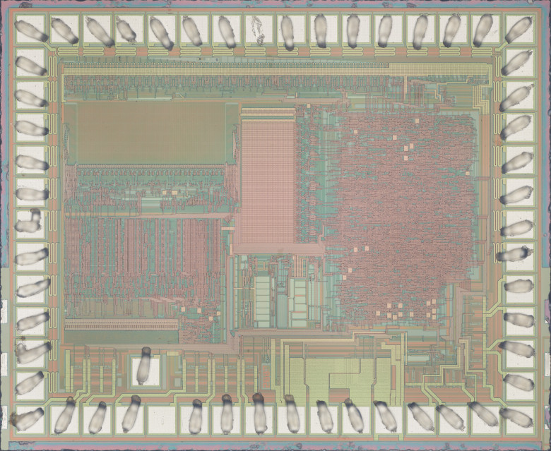
Full resolution

It has exactly the same architecture and almost the same die area, only the layout differs slightly. 3 KB of ROM, 160 B of RAM. Again, no identification marks, only the year(?) — 2003.
And here is the main culprit, modestly named Super Brick Game E-23 PLUS MARK II 96 IN 1 from the Taiwanese company E-Star:
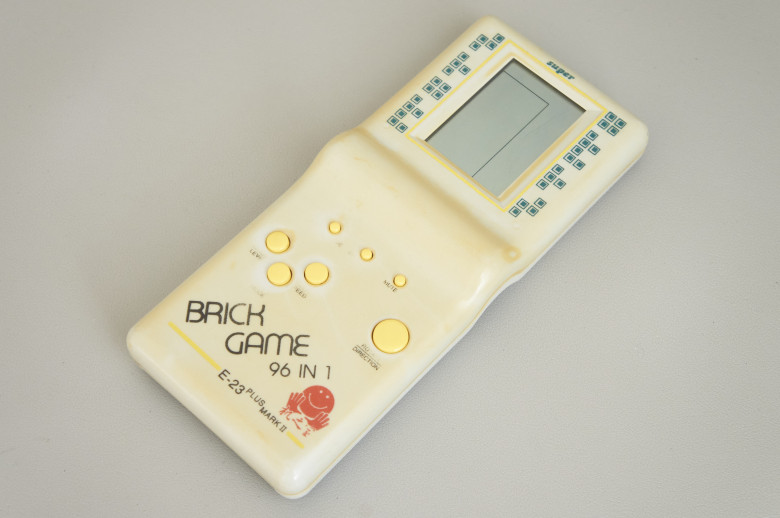
Super Brick Game E-23 PLUS MARK II 96 IN 1
The blob of encapsulant was much larger than on the previous two units, so decapsulation took me half an hour, but the result was worth it:
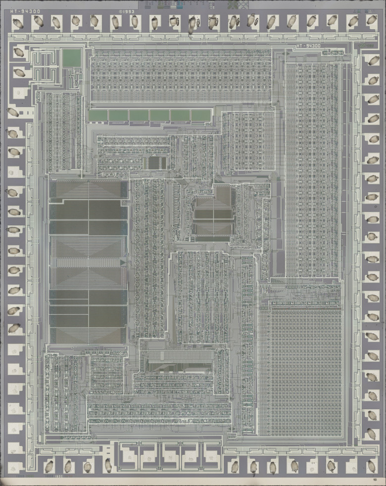
Full resolution

The old faithful HT-943 (aka HT443A0), only one year older than the example from the previous article.
Editor's insertion: DATASHEET PDF
For comparison, I made a group photo of the dies:
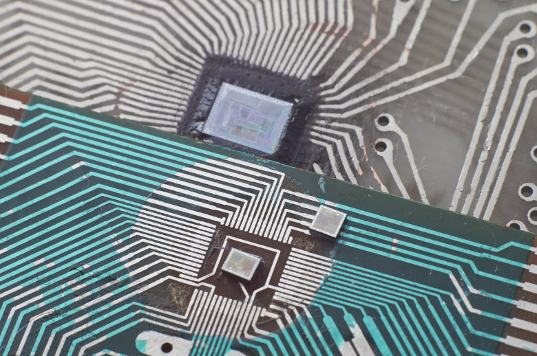
Microcontroller dies used in Brick Game, 1993, 2003, and 2008 (left to right)
Of course, it is too early to draw conclusions from just four units, but we can tentatively suggest that the main platform for Brick Game in the early and mid-1990s, when they were still produced in Taiwan, was 4-bit Holtek microcontrollers. By the late 1990s to early 2000s, when these toys started being mass-produced in China, the main platform switched to something closer to local manufacturing.
Reading the ROM
Naturally, my primary interest was the ROM, but at first glance it was disappointing — practically unreadable: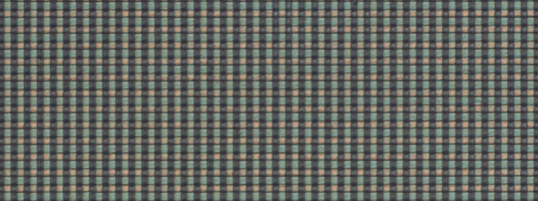
Photo of a ROM section under direct illumination.
Fortunately, it turned out that if the die is illuminated at an angle, the result becomes much better, though still not perfect:

Photo of a ROM section under angled light from a vertical illuminator.
Now the boundaries between "normal" transistors and those with an increased oxide thickness under the polysilicon layer are clearly visible. This is done to raise the transistor's threshold voltage, effectively preventing it from turning on (so you can consider it absent). In the next image, red dots mark the "normal" transistors, whose gate oxide layer allows them to be switched by the selection signal from the decoder:

How can we now turn this mess of bits into a sequence of bytes, or in other words, obtain a ROM image that we can actually work with?
In the previous article I touched on this topic briefly, but here I will explain in more detail, especially since the task turned out to be more difficult than I expected.
Let’s examine the ROM and its surroundings in more detail:
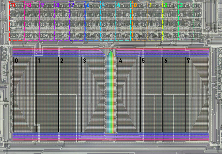
As I noted before, the bits of each byte are grouped together, which in the image above are marked with black rectangles. To read a byte correctly, you need to determine the bit significance (MSB/LSB). This can be done by tracing the internal bus (to which each group is connected) to the instruction decoder, where the significance is reconstructed using the instruction descriptions in the datasheet. The bit number determined in this way is labeled on the image.
At the top, you can distinguish 12 repeating groups of transistors (marked with colored rectangles). From each of these, a pair of signals — direct and inverted — runs along the decoder line around the ROM (marked with lines corresponding to the group colors). It is natural to assume that these lines define the 12-bit address of the byte being read, while the transistor groups form the circuits for the instruction counter registers, the stack (which is one-level here), and some auxiliary logic. To determine the correct byte order, it is necessary to figure out how the decoder lines correspond to the sequence of address bits. This is slightly more complex than reading individual bit significance. All 12 address bits are connected to an 8-bit internal bus, whose significance has already been established. This means that some of the bits (the leftmost and rightmost four groups) share the lower bits of the bus among themselves. Therefore, it was necessary to additionally analyze the control lines of the registers — they fully match for the right eight groups and differ for the left four. This suggests that the left four address bits are fed into the instruction counter separately from the eight right bits, from which I assumed they are the most significant bits. The address bit numbers are also labeled in the image.
There are two details I could not determine without reconstructing the full circuit: which line of the decoder pair carries the direct signal and which the inverted one, and the same for the bits themselves. This gives 2 variants of the ROM read order and 2 variants of reading a byte — perfectly acceptable.
In practice, I ran into some problems. Initially, I manually read about ten bytes for each variant, disassembled them, and saw nothing I expected. Based on the datasheet, I expected to find something like an unconditional jump at address 0, from which the microcontroller starts after reset. I also expected to see unconditional jumps at addresses 4 and 8, where interrupts land, or in the worst case a reti if interrupts are not used. But no — one variant was stranger than the other, so I had to recheck a bunch of less likely ROM read orders that didn’t fit the theory above. Having achieved nothing, I picked one of the first four variants, which looked more or less normal, and continued reading the ROM, gradually confirming that it was indeed the correct read method. It turned out the firmware authors completely ignored interrupts and even used some unexpected instructions like decrementing a memory cell right at startup and writing 0xE to port PA, which is physically unconnected:
000:    dec [R3R2]                      ;0F
001:    timer on                        ;38
002:    mov A, 0xE                      ;7E
003:    out PA, A                       ;30
004:    mov R1R0, 0xFF                  ;5F0F
006:    in A, PP                        ;34
007:    ja0 04C                         ;804C
009:    mov A, 0xF                      ;7F
00A:    call E67                        ;FE67
00C:    jmp 002                         ;E002
Emulator
Once I was confident that I was on the right track, I continued decoding the ROM while simultaneously debugging the emulator I had started writing a bit earlier. After several days of work, the firmware was fully recovered, the emulator was largely debugged, and obvious errors in the ROM image were corrected. Finally, I saw the cherished “01” on the display, experiencing roughly the same feelings as Victor Frankenstein shouting, “It’s alive!”
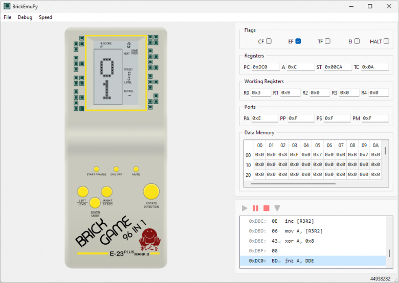
Brick Game Emulator
Of course, at first it wasn’t so pretty — at that time, I had only added part of the game field from the display segments. By the way, while reconstructing the segment map, I was struck by how irregularly they are arranged: for one digit, the segments are addressed one way, for the neighboring digit — another, part of the game field one way, the other another — I don’t envy the programmers who wrote code for this display.
The emulator is still rough (for example, there’s no sound at all), and it’s not certain I’ll finish it, but even now it can be quite helpful for exploring the firmware, if someone wants to write their own emulator or look for possible Easter eggs. You can also just play it and feel nostalgic :) The application supports basic debugging tools; the contents of all registers and RAM can be changed on the fly. It is written in Python using PyQt6, so it can run on any OS supported by that library (Linux, Windows, and macOS). The source code is available on GitHub, where you can also find the firmware image.
There are most likely still some bugs, so if you have the same model of Tetris and notice a difference in behavior from the original, please let me know — I’ll try to fix it.
Continued
>> Home