Author: Azya
Posted: 2023-10-20 08:06
Original: Article link
This small investigation was prompted by a recently published article on Habr, in which the author suggested that the famous 90s "Tetris" handhelds might have used a 4-bit Holtek HT1130 microcontroller. I was quite surprised (and motivated) that, apparently, no ROM dump has yet been made and, accordingly, no emulator exists for this line of games.
The assumption that Brick Game is based on the Holtek HT1130 has one weak point — the HT1130’s display driver can only control 128 segments, whereas a typical Brick Game has 200 (10x20) segments just for the game field. So where did the information about the Holtek HT1130 come from? A bit of googling led me to the primary source: a 2015 article, where the author mentions finding a datasheet for one variation of Brick Game — "Super Brickcal 9 in 1" — which runs on an HT113LA and differs from the classic version by having a smaller game field. He notes that the Holtek HT113LA is a private variant of the Holtek HT1130, on which, in addition to Super Brickcal, many other simple portable LCD games are built.
But I am interested in the more common versions of Brick Game — the recognizable cases with a middle curve, usually marked with the letter E and several digits. For example, ES-118 and E-88, as in the photo below:
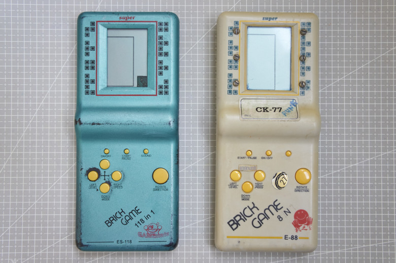
Research subjects
I deliberately bought these well-worn specimens for dissection. The E-88 was listed by the seller as defective, and among Brick Game enthusiasts, it is considered one of the most classic versions, so I’ll start with it.
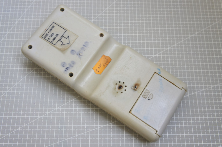
It had a hard life
1 hour 5 rubles :) is that a joke, or was someone really willing to pay for an hourly Tetris session?!
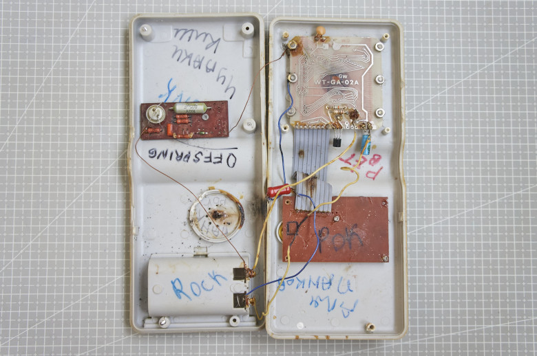
"Welcome to Americana"
Wow. Inside, one unexpectedly sees a rich internal world of the previous owner. Punk not dead!
Here is the chip I’m interested in, visible through the PCB:
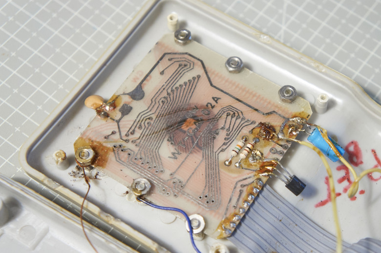
Main board of E-88
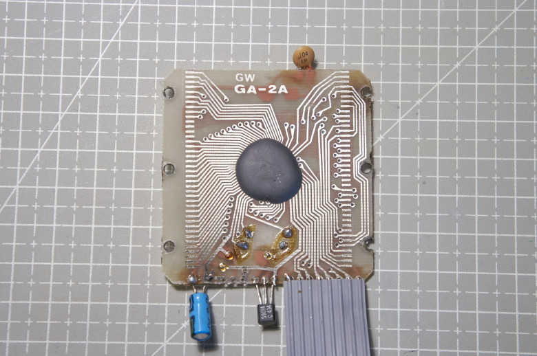
Main board of E-88
A black drop of encapsulating compound securely protects the microcontroller die from the outside world, and freeing it is quite a nontrivial task. The most reliable method would be to dissolve it in nitric acid, but such methods do not appeal to me for home work. Therefore, I chose a simpler, though less reliable, decapsulation method — thermal.
Decapsulation
The idea is as follows — we separate the entire drop along with the die from the PCB, then heat it over an open flame. As a result, the compound becomes brittle, allowing the bulk of it to be removed mechanically. Residual compound on the die surface is removed with dichloroethane (commonly sold as plastic glue).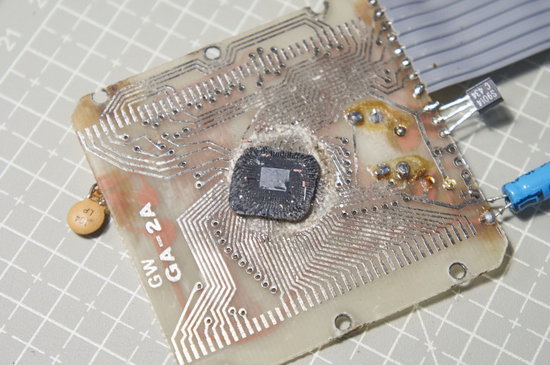
Underside of silicon die surrounded by compound
As I mentioned, this method is not very reliable (plus I lack experience), and unfortunately, during separation, the die cracked into two pieces :( Moreover, the main damage “luckily” fell on the ROM area, so I was unable to read it this time. So, here it is, the brain of the Brick Game E-88 (in full resolution):

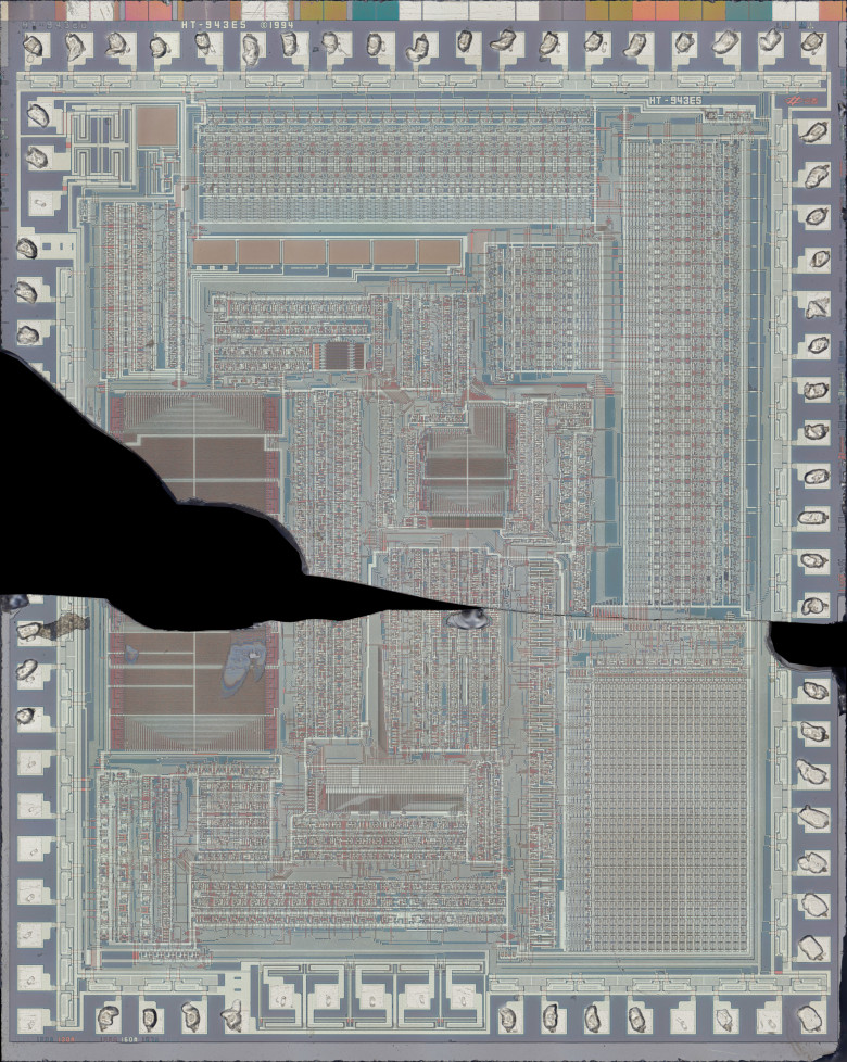
Die photo of the Brick Game 8 in 1 E-88 microcontroller

The HT-943E5 die marking immediately catches the eye, showing a mask date of 1994 and a small chip-art logo of Holtek.
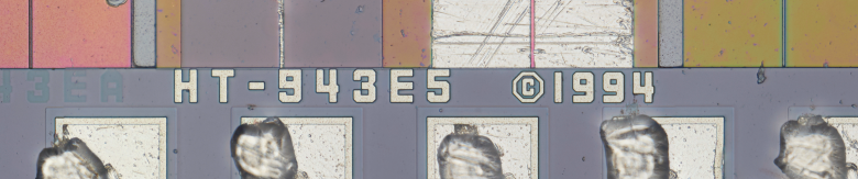
Marking and date
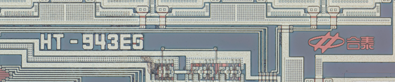
Marking and Holtek logo
This confirms that the classic mid-90s Brick Game runs on a Holtek microcontroller. What remains is to determine exactly which one.
Naturally, I immediately googled HT-943. The closest I found was the 8-bit HT-948, but it doesn’t really match what we see in the die photo — 16 KB ROM vs. 4 KB, 3328 bits RAM vs. 640, the number of controllable LCD segments still doesn’t match, and the 4-bit Super Brickcal hints that this is likely a 4-bit processor. In fact, someone more experienced could probably determine the ALU width from the die photo, but I am a complete amateur in microelectronics.
In the end, I went directly and downloaded all datasheets for 4-bit Holtek microcontrollers I could find (fortunately there are only a couple dozen publicly available), and eventually found the perfectly matching variant — HT443A0.
Editor's insertion: DATASHEET PDF
Judge for yourself: the number of LCD segments (40) and total pins (8) matches what can be recognized in the die photo, as do the 160 RAM nibbles plus 80 LCD RAM. Most importantly, the datasheet shows the die pin positions and dimensions, which exactly match our specimen.
Now I’ll try to play the role of a homegrown Ken Shirriff and annotate what I recognized on the die. Again, I remind you that my microelectronics knowledge is superficial, so I may have made mistakes in my assumptions (it would be great if knowledgeable readers could correct and supplement me in the comments).
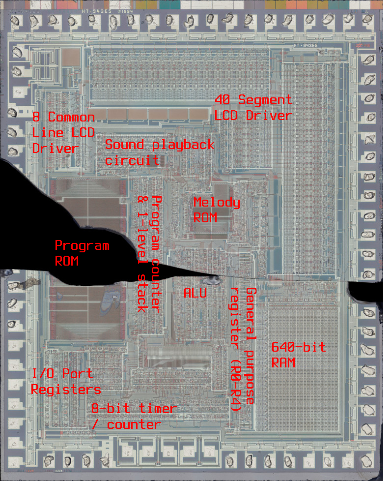
Let’s examine the ROM in more detail:
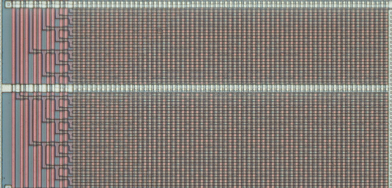
1/16 of the ROM
On the transistor grid, inhomogeneities are clearly visible, which encode individual ROM bits. Simply put, where a horizontal line (doped layer) intersects a pink vertical area (polysilicon layer) — it’s a 1, where it intersects a greenish area — it’s a 0. On the left, the decoder for the 6 most significant address bits is visible (the 6 least significant address bits decoder is located between the upper and lower ROM sections in the damaged area and is not visible in the photo). If you look closely, all horizontal lines converge in the upper-left corner — from there, one bit of the byte at a given address goes to the data bus. Each ROM segment like the one cut out above (there are 8 in total) and its mirrored reflection on the right contains every n-th bit of all 4096 bytes of ROM. And this is actually bad, because bits from the middle of each ROM byte are destroyed. Even part of the firmware cannot be read from this die.
While I wait for new donor chips for decapsulation, we do have a completely intact ROM for melodies, so let’s try to decode at least that.
Melody ROM
From the datasheet, we know that the HT443A0 supports 16 separate melodies, each of which can be a sequence of tones, noises, or percussion hits. Melodies 1–12 support up to 32 notes, and 13–16 up to 64. Unfortunately, the bit width of each note is not stated, but we can calculate it: visually, there are 4480 bits in the melody ROM, and according to the datasheet, there are 640 stored notes. Therefore, 4480 / 640 = 7 bits per note.To read the ROM, we need to determine how bits correspond to specific notes, and notes to melodies. For this, we can try analyzing the decoders that control note and melody selection.
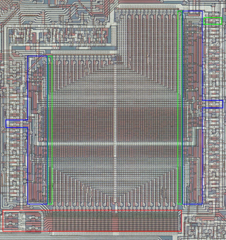
Melody ROM with highlighted note and melody decoders
In red is a 5-bit decoder that selects one of 32 pairs of vertical lines. It’s logical to assume that each of the 32 notes is stored in one pair of vertical lines. In blue is a 4-bit decoder that selects 1 of 16 sets of 7 horizontal lines (7 bits per note). One more 1-bit decoder, highlighted in green, allows addressing an additional 32 notes for double-length melodies.
I’ll try to illustrate this messy explanation by reading the first note of the first melody. First, the metal layer must be etched, as it hides part of the ROM. I used a low-temperature aluminum solder flux (composition unknown). Unfortunately, etching affects other IC layers, causing uneven color changes (depending on layer thickness), making reading the ROM quite difficult. No automation — all 4480 bits must be marked manually :(
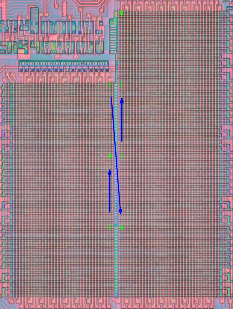
ROM with metal layer removed
In the photo, the bit values of the first note of the first melody are marked, with reading order from most to least significant indicated by arrows.
And here is the entire first melody:
1010110
1101011
0110101
1011010
1101101
1110110
1111011
0111101
1011110
1101111
0110111
0011011
0001101
1000110
1100011
0110001
1011000
0101100
0010110
1001011
0100101
1010101
1101001
1110100
0111010
1011010
1101110
1110111
0111011
0011101
1001110
1100111
For example, the note 1111111 shifts in 8 steps:
1111111
0111111
0011111
0001111
0000111
0000011
0000001
1000000
Now we can understand what sound the first melody contains — it is the sound played when a piece moves horizontally in Tetris.
And what about Korobeiniki? It occupies two 64-note melodies, the 13th and 14th. Here is the beginning of the famous melody with the corresponding frequencies labeled.
0111010 - 1092Hz
0111010 - 1092Hz
0111010 - 1092Hz
0111010 - 1092Hz
1100011 - 819Hz
1100011 - 819Hz
0101100 - 886Hz
0101100 - 886Hz
1010010 - 993Hz
1010010 - 993Hz
1010010 - 993Hz
1010010 - 993Hz
0101100 - 886Hz
0101100 - 886Hz
1100011 - 819Hz
1100011 - 819Hz
1101111 - 728Hz
1101111 - 728Hz
1101111 - 728Hz
0000000
1101111 - 728Hz
1101111 - 728Hz
0101100 - 886Hz
0101100 - 886Hz
0111010 - 1092Hz
0111010 - 1092Hz
0111010 - 1092Hz
0111010 - 1092Hz
1010010 - 993Hz
1010010 - 993Hz
0101100 - 886Hz
0101100 - 886Hz
In addition to the melody ROM, there is another, smaller ROM, also related to the music circuit:
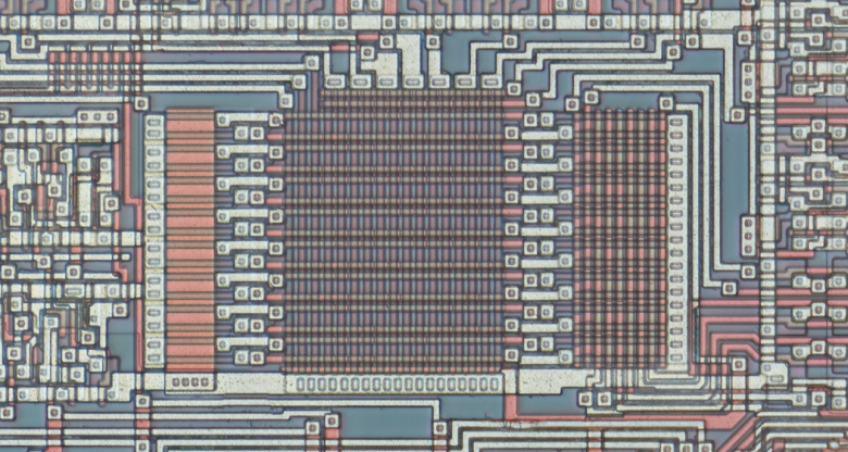
I haven’t analyzed it yet, but apparently it contains the tempo divider for each melody, the “instrument” type, and probably something else.
In the near future, I plan to finally extract the entire die from under the encapsulating compound and dump the firmware image. After that, creating an emulator won’t be far off.
Continued.
>> Home